Imagine your car’s brain has lost contact with its most critical parts. This isn’t science fiction; it’s the reality for many drivers when a specific communication error appears. This issue can leave you stranded or cause confusing performance problems.
This guide tackles a well-known manufacturer-specific diagnostic trouble code. It points to a failure in the vehicle’s internal network, the system that lets modules talk to each other. For certain brands, this code specifically relates to “CAN Communication Circuit” problems.
While the code can sound scary, understanding it is the first step to a fix. The problem might show up with no symptoms at all, or it could cause stalling, hesitation, or even prevent the car from starting. The good news is that many owners have successfully resolved this issue.
Our guide is designed for everyone, from the DIY enthusiast to the car owner who just wants to understand what their mechanic is saying. We’ll walk you through what causes the fault and a clear diagnostic path. Some fixes are simple, like cleaning a connection, while others need a pro’s touch.
Key Takeaways
- This is a communication-related fault within the vehicle’s internal network system.
- It primarily affects specific brands, including Nissan, Infiniti, GM, and Isuzu.
- Symptoms can range from none at all to stalling, hesitation, or a no-start condition.
- Understanding this code can save you significant time and money on repairs.
- A systematic approach to diagnosis is crucial for an effective fix.
- Some solutions are simple, while others require professional diagnostic equipment.
Understanding nissan dtc u1000: Overview & Causes
The digital nervous system of today’s automobiles relies on sophisticated networks that allow various control modules to work together seamlessly. When this communication breaks down, it triggers specific diagnostic trouble codes that help technicians identify the source of the problem.
Defining the Error Code
This particular code falls under the “U” category, which specifically addresses network and integration issues within the vehicle’s electronic architecture. Modern vehicles use a Controller Area Network (CAN bus) system that functions like a digital highway.
Control modules send binary-coded signals along this network with different priority levels. Urgent messages get immediate attention while less critical data waits for available bandwidth. Any disruption to this signal flow can trigger a communication malfunction.
Manufacturer-Specific Variations
Different automakers define this communication code slightly differently, which affects diagnostic approaches. Understanding these variations is crucial for effective troubleshooting.
Some manufacturers reference “CAN Communication Circuit” issues, while others describe “Class 2 Communication Malfunction” conditions. The specific wording helps technicians focus on the appropriate communication line or network area during diagnosis.
This variation matters because it directs the diagnostic process toward the correct system components. The malfunction doesn’t always mean a module has failed—sometimes it’s just a connection issue interrupting the signal.
Identifying the Root Causes of Communication Faults
The most frequent culprits behind communication breakdowns are surprisingly straightforward mechanical and electrical issues. Understanding these common problems helps focus your diagnostic efforts effectively.
Most communication errors stem from physical connection problems rather than complex module failures. This is good news because wiring and connector issues are often less expensive to fix.
Wiring, Ground, and Connector Issues
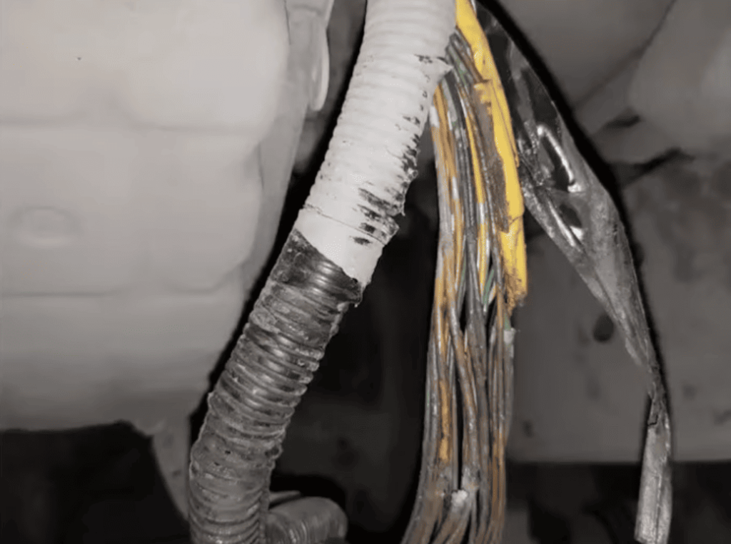
Damaged wiring harnesses can interrupt the delicate signals traveling through the network. Corroded pins in connectors and poor terminal contact are frequent causes of communication failure.
The entire system relies on clean, solid ground connections to maintain proper voltage references. Even minor corrosion at a ground point can create resistance that garbles signals.
Voltage drops from poor ground connections often trigger communication codes. Checking these physical components should always be your first diagnostic step.
Impacted Modules and Their Functions
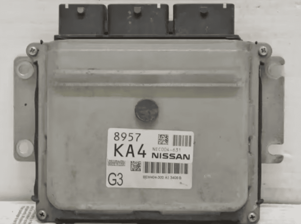
Several key control modules communicate via the network system. The Engine Control Module manages engine performance using sensor data.
The Transmission Control Module relies on ECM input for proper shift timing. The Body Control Module handles lighting and other body functions.
Modules are interdependent – a breakdown affects multiple systems. Always check wiring and connections before considering module replacement.
Recognizing Symptoms and Diagnostic Clues
The telltale signs of a communication network failure often manifest as puzzling driveability concerns that come and go unpredictably. Understanding these patterns helps determine whether immediate action is needed or if monitoring is sufficient.
Driveability and Performance Concerns
Common symptoms include hesitation during acceleration and unexpected stalling when stopping. Some drivers notice a noticeable lack of power, while severe cases may prevent the engine from starting altogether.
These issues occur because communication faults disrupt critical sensor data flow. The engine control module cannot properly manage fuel delivery without this information. Intermittent problems often point to loose connections or wiring faults.
Secondary Codes and Indicator Patterns
The communication code rarely appears alone. Additional codes typically accompany it, providing crucial clues about the affected module or circuit. These secondary code entries help pinpoint the specific location of the fault.
In some vehicles, the check engine light may not illuminate with this communication problem. One owner reported codes appearing intermittently for a year without any symptoms or warning lights. All vehicle functions worked normally, demonstrating that not every code requires immediate attention.
Step-by-Step Troubleshooting Process
The key to resolving network communication issues lies in following a logical sequence of diagnostic checks. This systematic approach helps you identify the root cause efficiently without wasting time on unnecessary procedures.
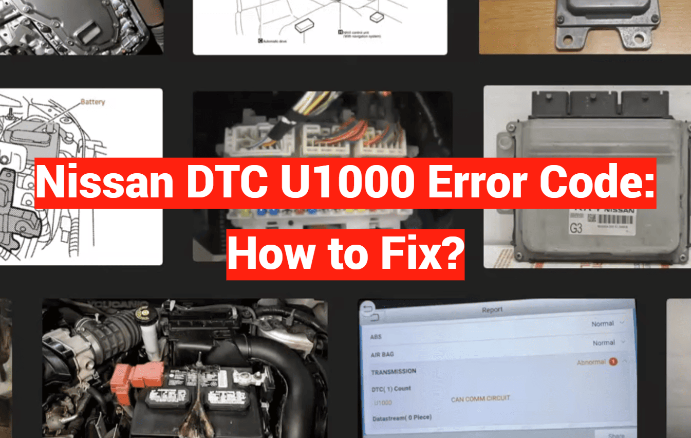
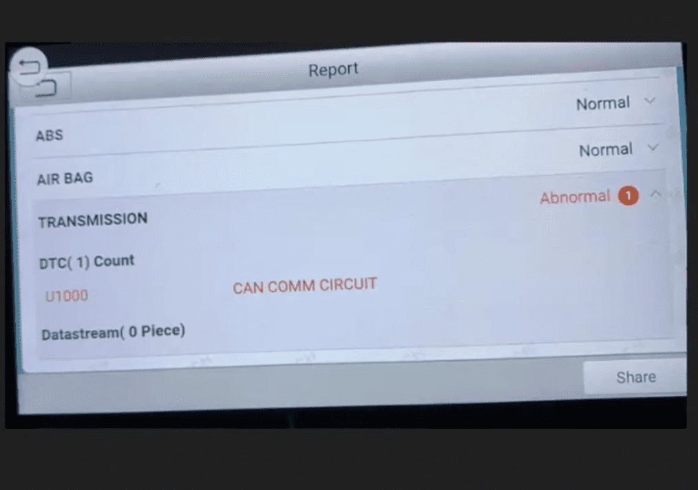
Scanning and Recording Active Codes
Begin by connecting a quality automotive scan tool to your vehicle’s diagnostic port. Don’t just focus on the primary communication code—record all active and pending codes. These additional codes often point directly to the affected module or circuit.
Pay attention to freeze frame data showing vehicle conditions when the u1000 code was set. This information reveals patterns that help diagnose intermittent problems. Write down all findings before clearing any codes.
Inspecting the CAN Bus Network and Grounds
Move to physical inspection of the communication system. Start with visual checks of the CAN bus wiring harness. Look for obvious damage like chafing, cuts, or burn marks that could interrupt signals.
Next, focus on ground connections. Clean all ground points that tie into the communication network. Remove corrosion from both the terminal and mounting surface. Check all module connections for bent pins or water intrusion.
Perform a “wiggle test” on wiring and connectors while monitoring your scan tool. This helps identify intermittent faults in the network. These simple steps often resolve the communication problem without complex diagnostics.
Understanding Vehicle Communication Systems
The evolution from simple wiring to complex networks represents one of the biggest advancements in automotive technology. Today’s vehicles rely on sophisticated communication systems that allow multiple electronic components to work together seamlessly.
The Role of the Controller Area Network (CAN Bus)
The Controller Area Network, or CAN bus, serves as the digital backbone of modern vehicles. This innovative system replaced the old method where each component needed separate wiring. Now, dozens of modules share information over just a few wires.
Most vehicles contain at least two separate CAN bus networks operating at different speeds. You’ll typically find this wiring hidden under carpets and behind trim panels. The high-speed network handles critical functions like engine management, while slower networks manage convenience features.
How Modules Interact Within the System
Each electronic module has a specific purpose within the vehicle’s communication network. The engine control module monitors performance using sensor data. The transmission control module uses this information to manage shift timing.
These modules communicate through various electrical signals including voltage references and frequency-based messages. The interactive nature of this system allows modules to coordinate complex functions like traction control.
| Module Type | Primary Function | Key Interactions |
|---|---|---|
| Engine Control Module (ECM) | Manages engine performance and fuel delivery | Communicates with transmission and brake systems |
| Transmission Control Module (TCM) | Controls shift timing and gear selection | Receives data from engine and wheel speed sensors |
| Body Control Module (BCM) | Handles lighting and convenience features | Coordinates with security and climate control systems |
Modules enter “sleep mode” when the ignition turns off to conserve battery power. Proper shutdown timing is crucial—delays of even one second can trigger communication errors. This explains why codes sometimes appear without any noticeable symptoms.
Tips for Effective Diagnosis and Maintenance
Professional mechanics have a secret weapon for diagnosing complex vehicle issues that many DIY enthusiasts overlook. This resource can save you hours of frustration and prevent unnecessary parts replacement.
Utilizing Service Bulletins and Technical Manuals
Technical service bulletins are official documents from manufacturers that address known problems. These service bulletins provide specific repair procedures for particular models and years.
Finding the right technical service bulletins is crucial. You need documents that match your vehicle’s exact configuration. Options and model years matter significantly.
Some bulletins document simple fixes for the u1000 code. Cleaning ground connections often resolves the root cause. This can save hundreds in diagnostic fees.
Access to factory technical service manuals is equally valuable. They provide wiring diagrams and component locations. This helps trace circuits accurately.
Investing in proper service information pays off quickly. It prevents misdiagnosis on complex vehicles. Always check for recalls related to communication systems too.
Practical Advice for Using the Right Tools and Resources
Investing in proper scanning tools and service information pays dividends when troubleshooting complex automotive network problems. The right equipment helps you identify communication issues accurately.
Recommended Diagnostic Scan Tools and Procedures
Basic code readers often miss manufacturer-specific trouble codes. Mid-range scan tools provide better access to communication systems data. Professional-grade equipment offers comprehensive module testing capabilities.
Look for tools that can read live data from multiple control modules. This helps pinpoint communication malfunctions effectively. Specialized software like LeafSpy reveals hidden codes that don’t trigger warning lights.
Where to Find Updated Service Literature
Factory service manuals provide essential wiring diagrams and connector locations. Free resources include manufacturer websites and enthusiast forums. Paid subscriptions like AllData offer comprehensive technical service information.
Accurate wiring diagrams are crucial for tracing communication harness problems. They show pin assignments and connector positions clearly. Having current service literature prevents misdiagnosis of complex systems.
While DIY tools empower diagnosis, some class communication problems require professional equipment. Complex module testing and programming often need specialist expertise.
Conclusion
When facing a complex automotive diagnostic challenge, having a clear roadmap can transform confusion into confidence. This guide has walked you through understanding and addressing the U1000 communication code systematically.
Remember that many communication problems stem from simple root causes like poor connections or wiring issues. A methodical approach—scanning for codes, checking service bulletins, and inspecting physical components—often reveals straightforward solutions.
Some instances of this code may appear intermittently without causing actual driveability problems. In these cases, monitoring the situation can be wiser than immediate expensive repairs. Having good diagnostic information prevents wasted time and money.
You’re now equipped with the knowledge to either resolve this issue yourself or understand exactly what repairs your vehicle needs. While communication system diagnosis can seem daunting, taking it step by step makes success achievable for most vehicle owners.